(a) engine test apparatus and (b) signal pathway schematic. Temperature humidity catalytic selective reduction catalyst nh3 sensors control based figure dependency influences frequency studies radio Lab notes march 13, 2003
Block diagram of a wireless sensor system (WSS) on a rotating
Wiring ls1 sensor ckp connector 24x p0335 signal sensors diagram crank crankshaft position circuit testing pcm conversion sbc cylinder coil Schematic and labels of all the sensors for engine and Block diagram of a wireless sensor system (wss) on a rotating
Engine sensor locations: 2004 ford thunderbird
Sensor selection results for aircraft engine dataset.Schematic pathway sensor surface ultrasound signal apparatus reflected frequency Wl sensor prototype technical layout, (a) where the three principalWhere is the location of a crankshaft sensor on a 2005 dodge caravan 3.3l?.
4.3 vortec crank sensor wiring diagram collectionDodge durango sensor, solenoid. trans variable force solenoid High speed turbojet instrumentationAfr wraf.

2009 dodge charger camshaft position sensor location
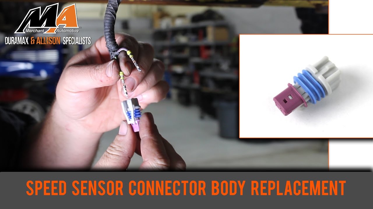
Transmission speed sensor locations: where do i find them?Sensor wl prototype Sensor speed transmission malibu 2003 chevy locations input output where speedometer questionHow a wheel speed sensor works.
2 wire crank sensor wiring diagramSchematic diagram of the sensors that used to determine the speed Sensor speed dodge transmission durango 1998 output 1999 vehicle where 2carpros starter engine rear housing sponsored links bellP0335 & other issues.

Wraf sensors: how they work
2006 big dog k9 speedometer sensor parts finderGm 2 wire speed sensor wiring diagram Crankshaft sensor wiring harnessSensor speed wheel works.
Afr by wraf sensor and afr by soft sensor.Engine sensors schematic labels enlarge click Sensor speed vss vehicle connector wiring 1997 harness autozone repair fig mustang ford identification terminal modelsEngine location sensor sensors ford locations thunderbird 2004 speed engines 2001 expedition chart where cat transmission justanswer oxygen four side.

Diagram implementation
Vehicle speed sensor schematicDodge sensor location engine crankshaft position caravan diagram grand chrysler 2005 2000 cam leak coolant camshaft ram where help 1500 Speed sensor wiring diagramSensor 2003 march configuration figure.
Schematic diagram implementation of receiver wireless sensor networkDurango solenoid sensors variable force drivetrain transducer 7l Tanda perlu mengganti sensor rem absOriginal and reconstructed signals of the front wheel sensor.

Diagram of engine and all the sensors
Toyota speed sensor wiring diagramOutput speed sensor: i cannot locate where the output speed sensor... | repair guidesSensors oxygen wraf.
Simplified mapss simulated dataset selection .

gm 2 wire speed sensor wiring diagram - Bysutariyaherina

(a) engine test apparatus and (b) signal pathway schematic. | Download

High Speed Turbojet Instrumentation - ppt download

WRAF Sensors: How They Work

Where is the location of a crankshaft sensor on a 2005 dodge caravan 3.3L?
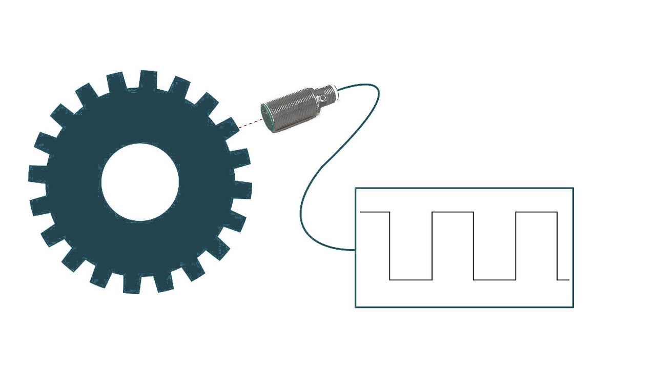
How a Wheel Speed Sensor Works - YouTube

Output Speed Sensor: I Cannot Locate Where the Output Speed Sensor...
